AdaShape alpha build 0.2.0 is out.
- Download the free alpha testing version on GitHub
This release adds several new ways to build shapes:
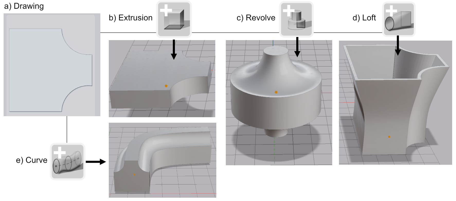
 Curves extend a profile along a path through points in space
 Loft joins stacked profile drawings into one shape
 Arrays repeat a part along a line or around a circle
 Split divides a shape by another shape, or into its separate pieces
It also adds a family of volumetric tools.
 Round rounds every edge.
 Offset grows or shrinks the surface.
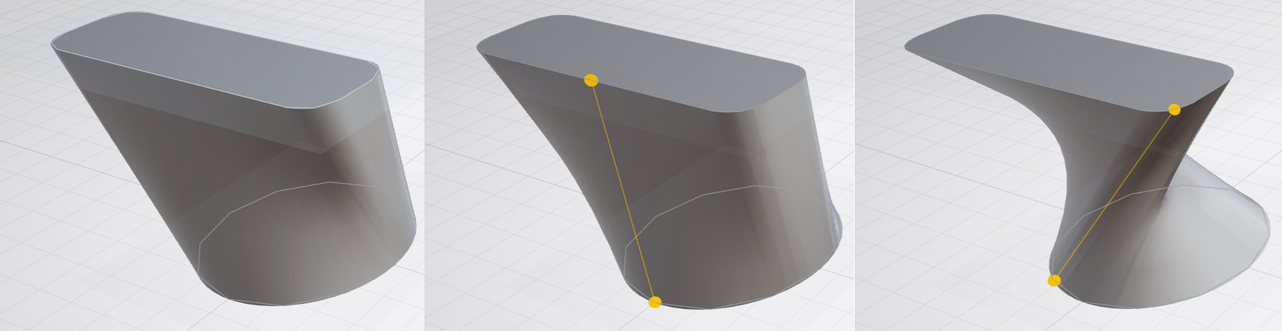
 Sweep merges two or more shapes into one solid, in the order you select them.
Every shape in the 3D view is a printable solid. Exports are watertight triangle meshes. You can preview the exportable mesh by turning on the wireframe mode in the main editor window.
There are also measure tools, a mirrored drawing mode, a way to recover a drawing from an existing shape, and a long list of smaller changes.
Let’s take a look at the headline features below.
Curve
|
Curve Creates a curve through the selected points |
Curve is a solid 3D shape formed by extending a 2D profile along a path.
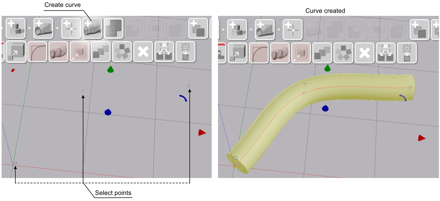
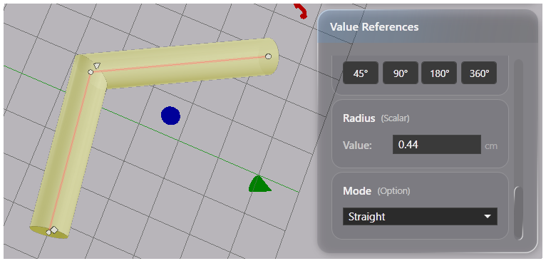
The curve path can be smoothed (Spline) from point to point or composed of straight segments. This is controlled by the curve’s Mode.
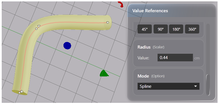
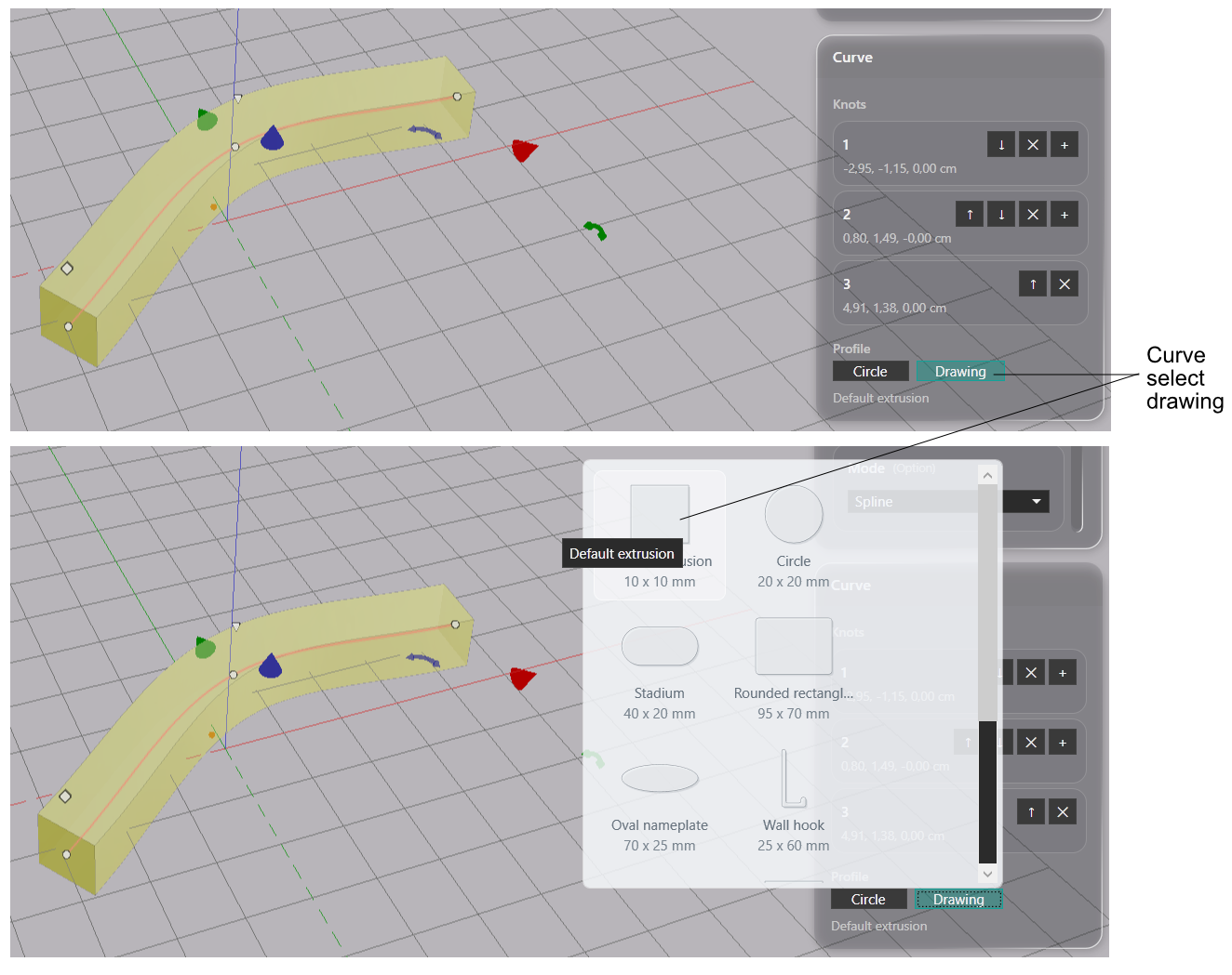
The curve’s Profile can be either a circle or a specific drawing.
Loft
|
Loft Fits shape to stacked drawings |
The loft tool connects drawing outlines in order into a single shape. The shape is either a solid object or a hollow shell that has a defined wall thickness.
Unlike a curve, a loft accepts a different drawing for each profile section. This makes the loft tool suitable for objects whose cross-section changes along one axis, such as a boat hull, a bottle, a funnel or a shoe.
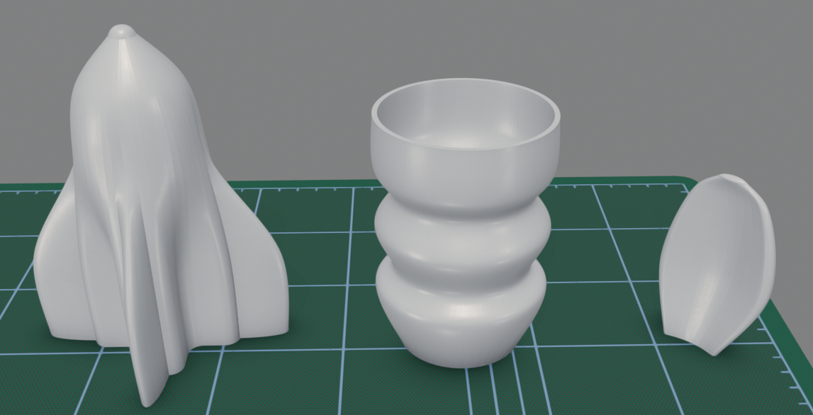
Loft has two specific editing modes reached from the main model view: a 3D loft editor and a profile editor.
Here we demonstrate the use of loft to model a shoe-like shape.
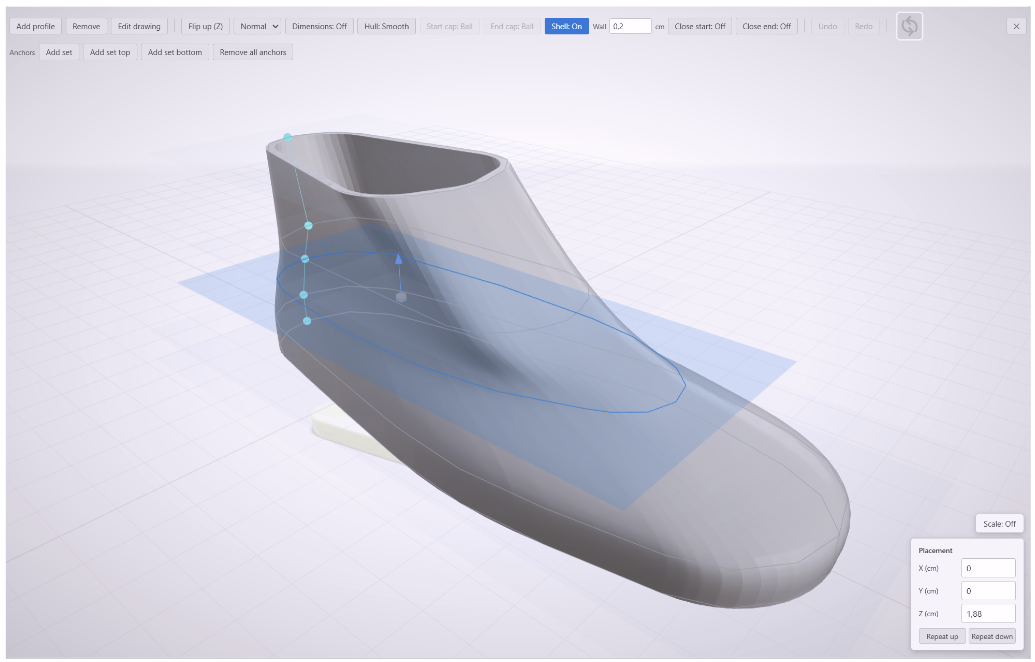
This is the 3D loft editor view. The shape of the shoe is defined by profile drawings at five distinct heights from the sole up to the ankle. They are connected into a single surface.
The shell is configured as hollow with a wall thickness of two millimetres.
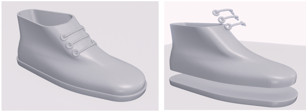
Back in the full model view, the finished shoe combines the loft upper with a sole and laces, which are separate shapes.
Anchors control how the surface flows between profiles that differ in shape or size. An anchor set marks one point on each profile, and the loft tool aligns the surface through those points. When you move an anchor, the loft tool realigns the surface through its new position. An anchor can be placed at any position along its profile.
Each profile is edited in the profile editor. The profile editor has the same tools as the drawing editor. It can display another profile as a tan reference outline while you draw.
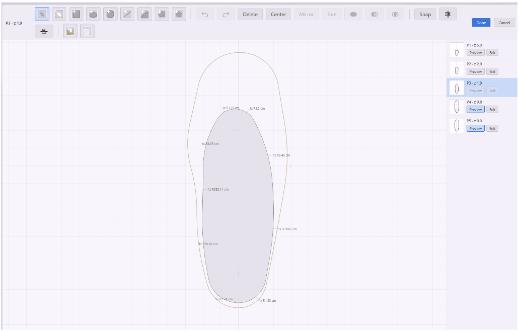
Note: all profiles of a loft are positioned flat along a single axis. You can move a profile horizontally and vertically but not tilt it.
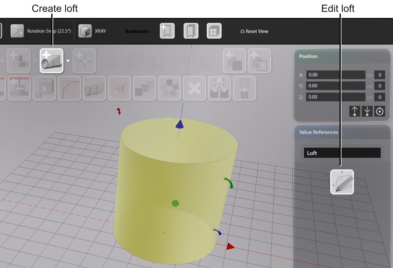
To try the loft tool, create a new loft and open the loft editor. Drag a profile along the axis to change its position. The profiles reorder by height. Double-click a profile to edit its drawing. Add an anchor set when the surface does not align between profiles.
Linear Array
|
Linear Array Copies laid out along a line |
Linear array repeats a shape along a line between start and end points. Moving the line changes how the array is laid out in any direction.
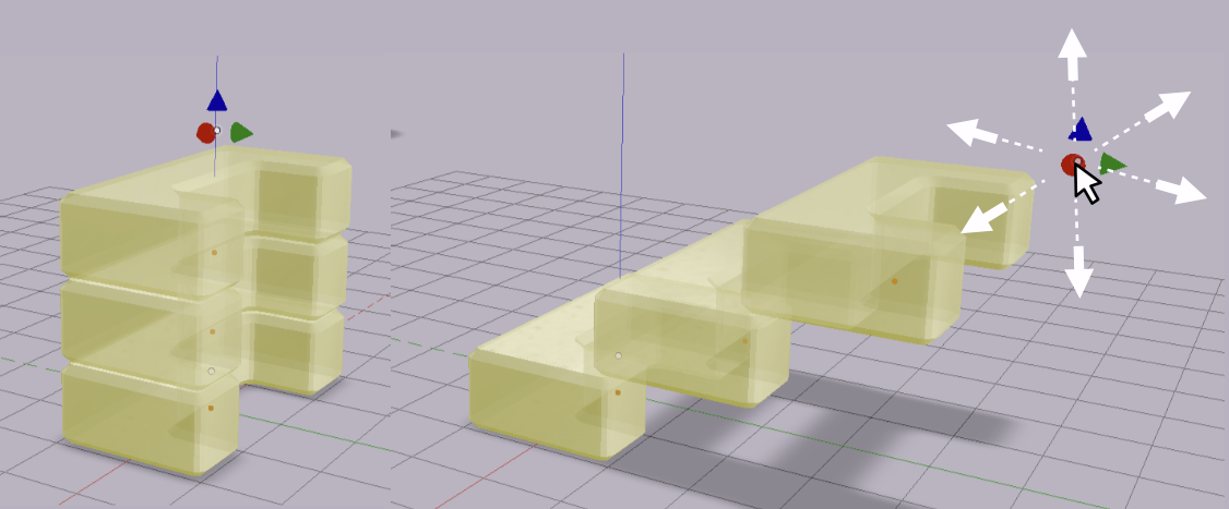
The Value References sidebar holds the array’s controls:
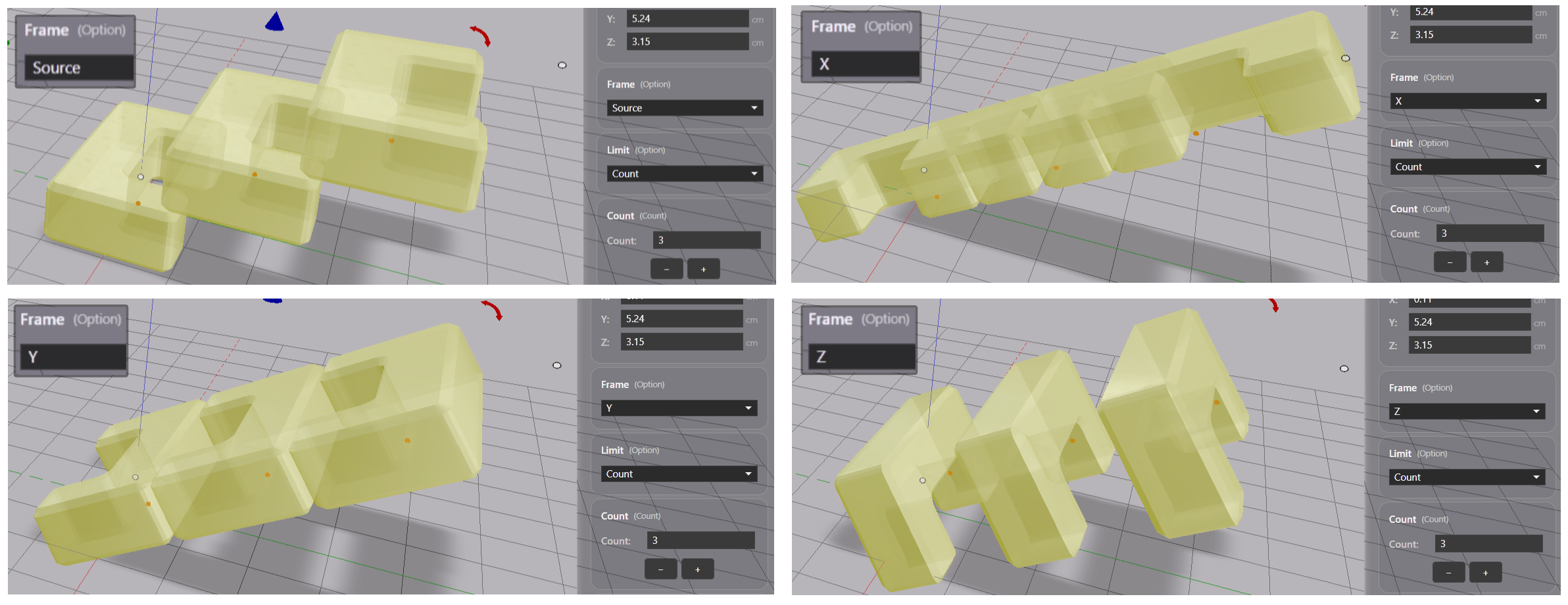
- Frame controls the orientation of the shapes. Source keeps the original shape’s orientation. X, Y, or Z turns that shape axis to follow the line’s direction.
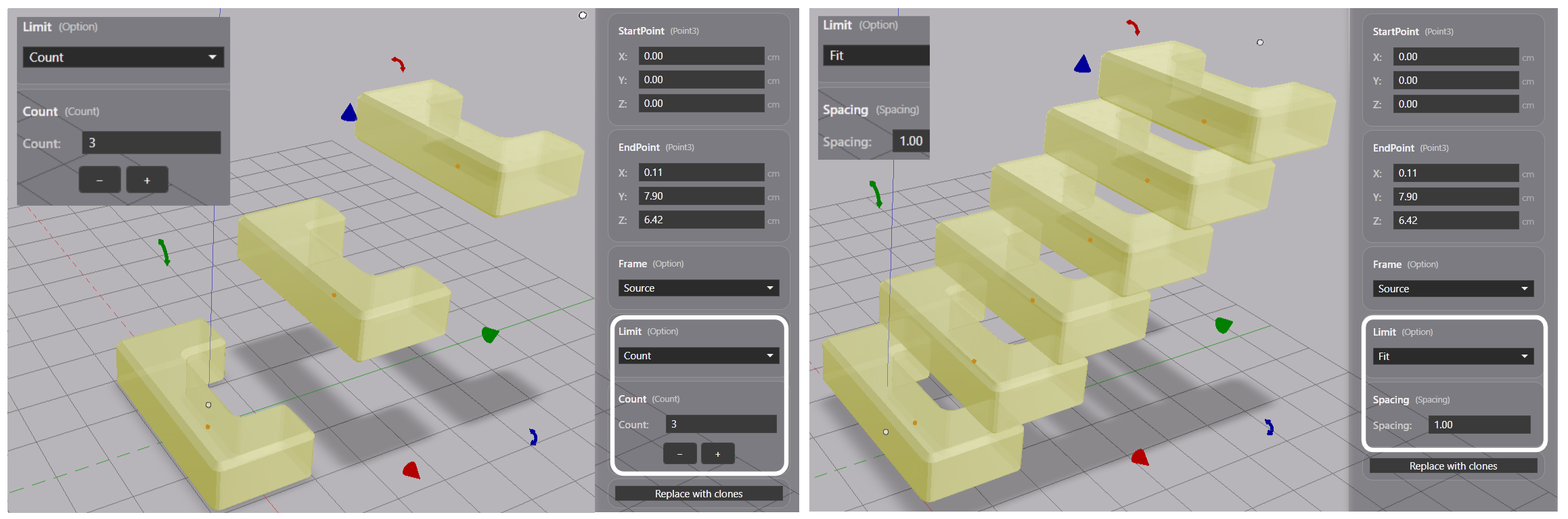
- Limit controls how many copies the array makes. ‘Count’ sets it to a specific number. ‘Fit’ creates as many copies as needed to fill the line. ‘Spacing’ controls how tight the copies are placed, relative to the size of the shape.
Circular Array
|
Circular Array Copies placed around a circle of given radius |
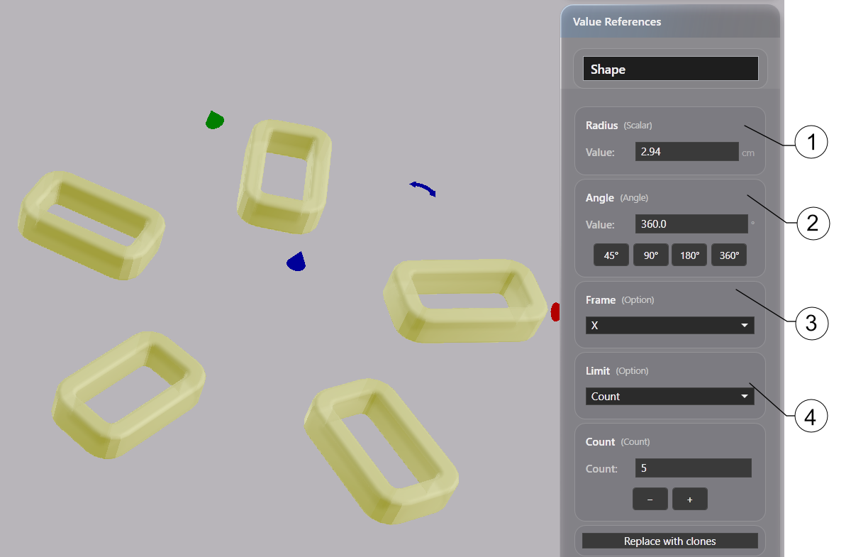
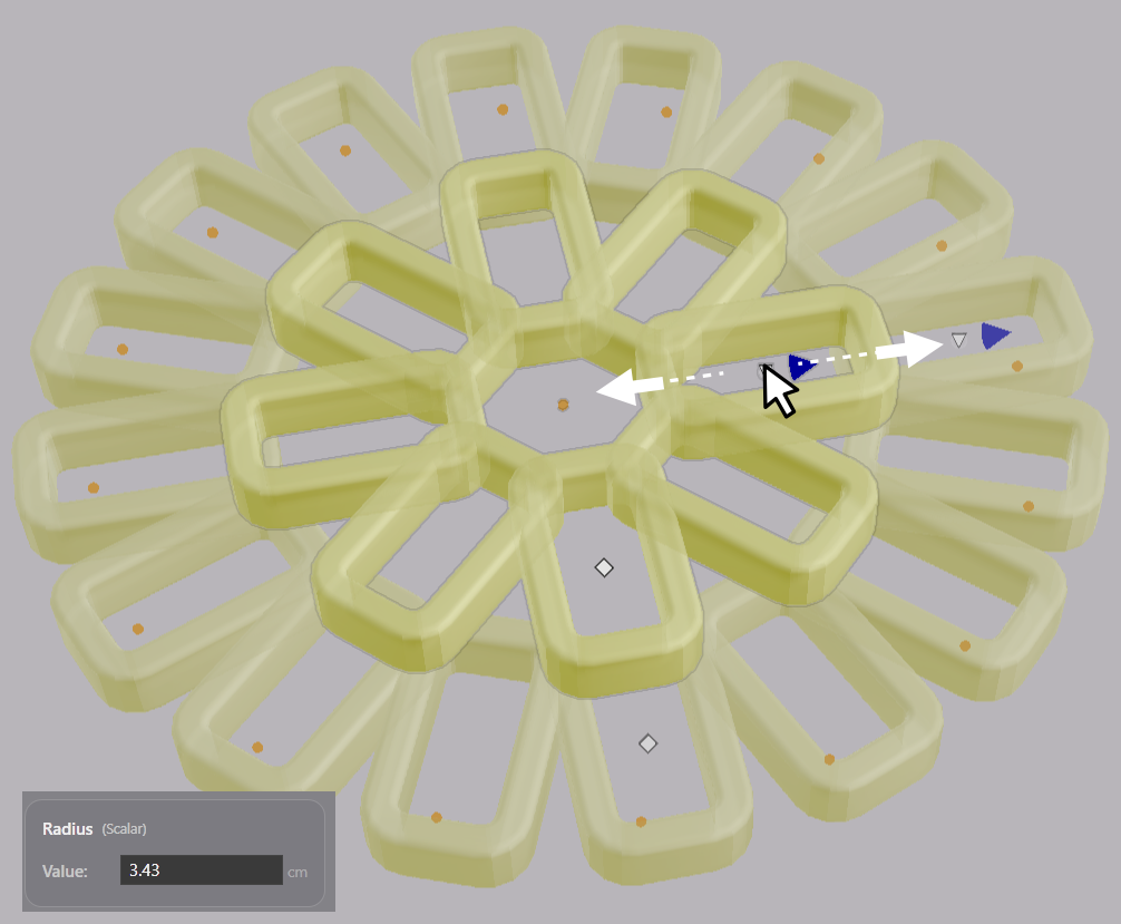
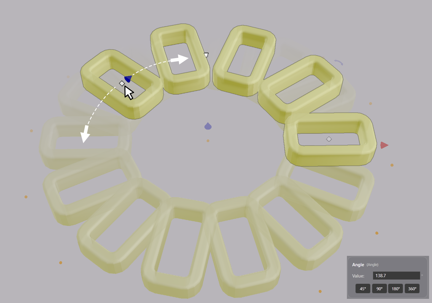
Circular array repeats a shape around a circle. Frame and Limit work as in the linear array. Radius controls the circle’s radius. Sweep angle controls the extent of the circle used for the copies: 360 degrees is the full circle, 180 degrees is half.
Boolean Split
|
Boolean Split Split the first object by the second into its outside and inside pieces |
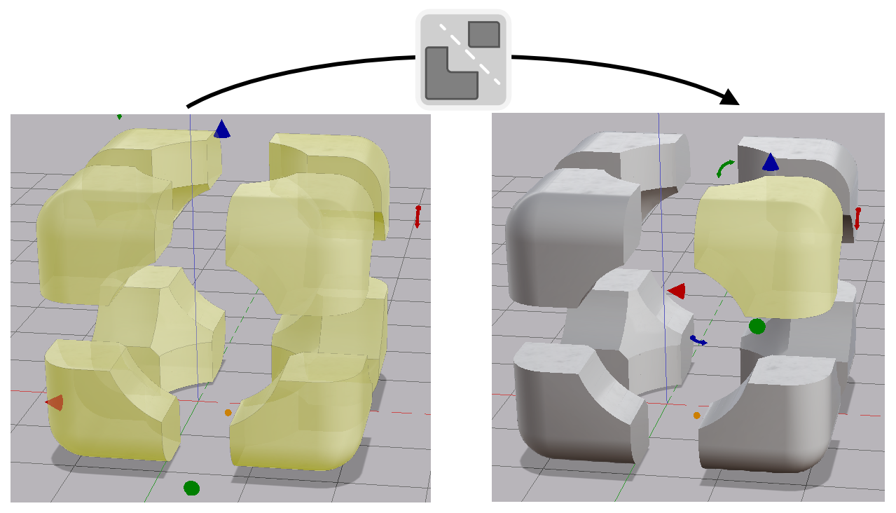
Divide one shape by another into two complementary pieces in one operation. Select two shapes and click Split. The first shape is replaced by two pieces: the part outside the second shape, and the part inside it.
Use Split to divide a part into printable halves, carve off a feature region, or make matched joint pairs.
Split Into Parts
|
Split into parts Break a shape into one part per disconnected piece |
Break a shape into its disconnected parts. Each disconnected piece becomes its own shape. In the example below the source shape is split into eight shapes.
Recover Drawing
 |
Recover drawing Turn a shape's cut through the ground plane back into an editable drawing |
Recover drawing saves the cross section of the selected shape where it crosses the ground plane into a drawing.
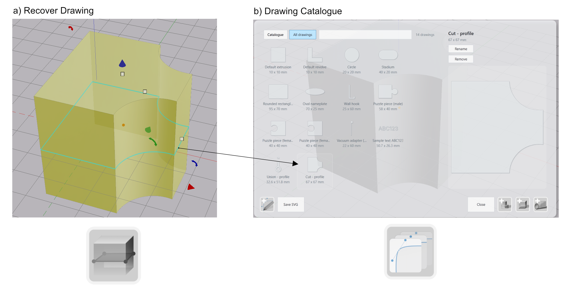
The created drawing can be found in the Drawing Catalog and can be used for all actions that support drawings: extrusions, revolves, lofts and 3D curve profiles.
Volumetric Tools
Volumetric tools modify the entire shape at once, or several shapes together. The tessellation resolution affects the coarseness of the result and the execution time needed per operation.
Rounding
|
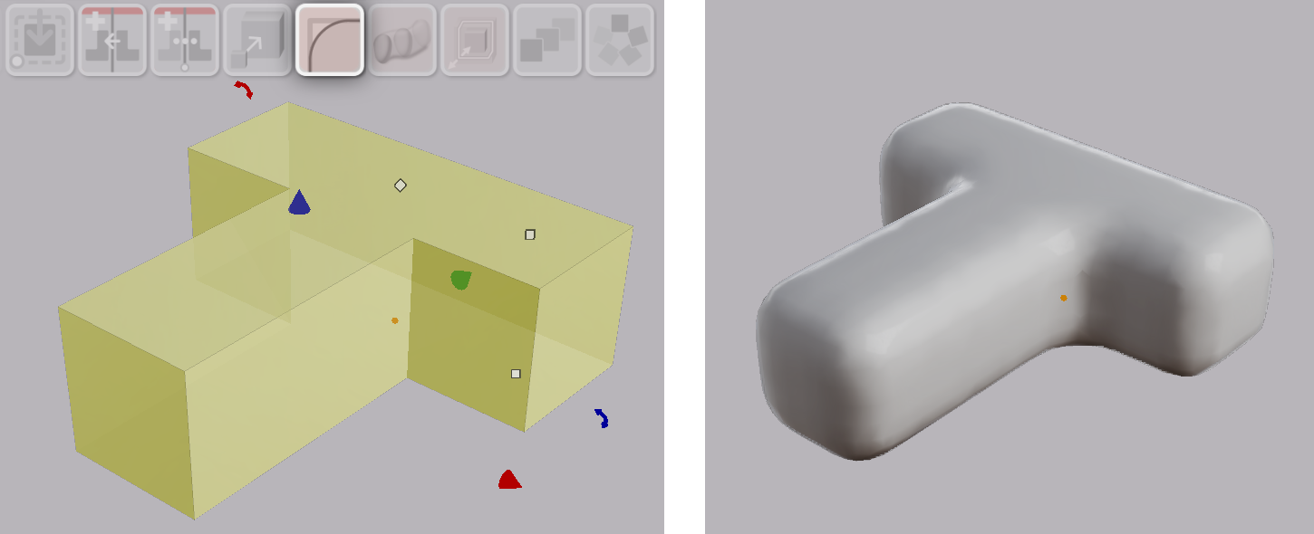
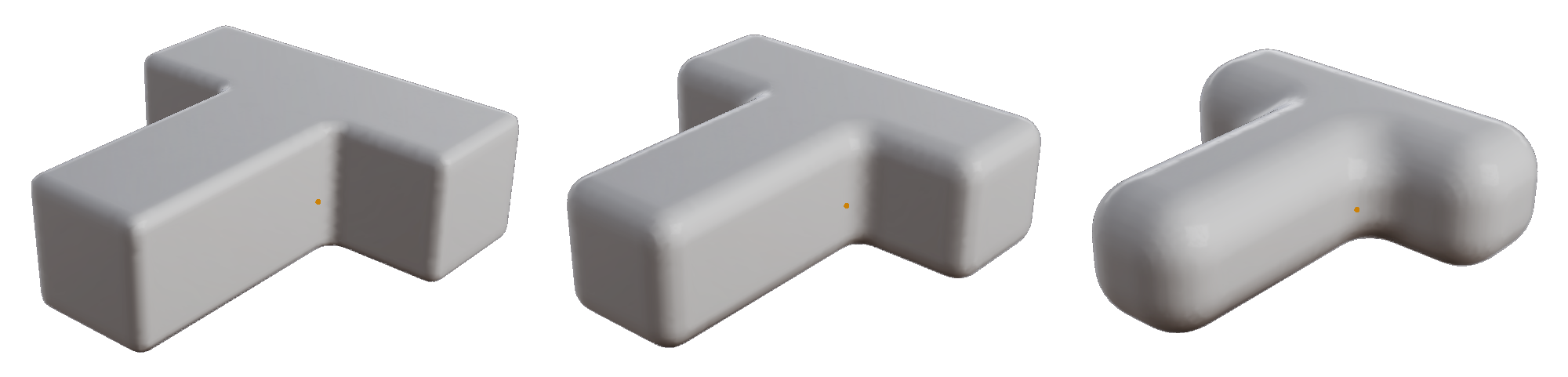
Rounding Round all edges of the selected shape with an editable radius |
Rounding fillets every edge of the selected shape with given radius. A case or a knob is more comfortable in the hand with its edges rounded.
Note: the radius applies to every edge. There is no per-edge selection.
Sweep
|
Sweep Merge an ordered selection of shapes into one solid that passes through each of them |
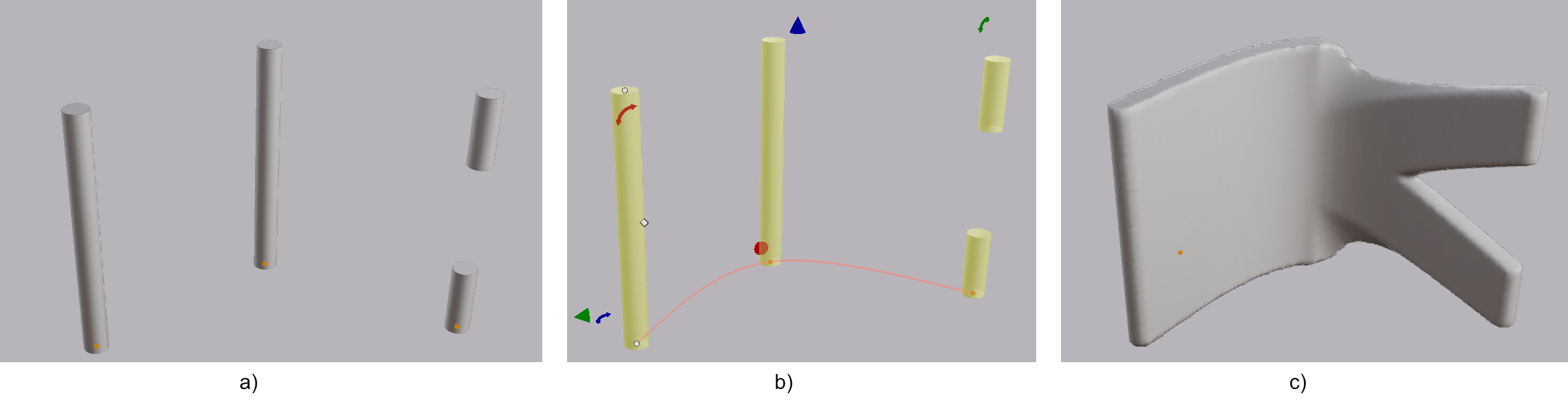
Sweep merges an ordered selection of shapes into one solid. The solid passes through each shape in the order you selected them. Select two or more shapes and click Sweep.
Note: Sweep needs round, thick shapes to work well.
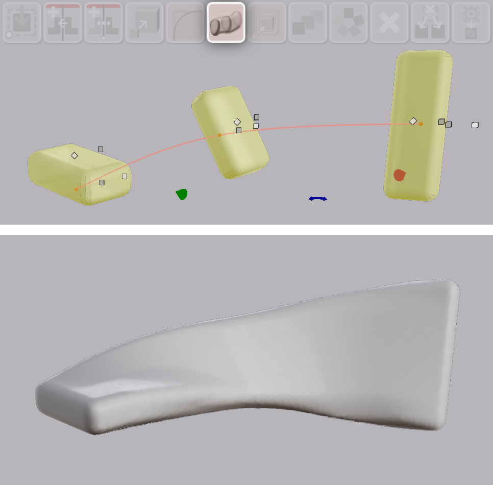
A source shape can have more than one volume. Sweep then produces a forking solid.
Surface Offset
|
Surface Offset Inflate or deflate the selected shape's surface by an editable signed distance |
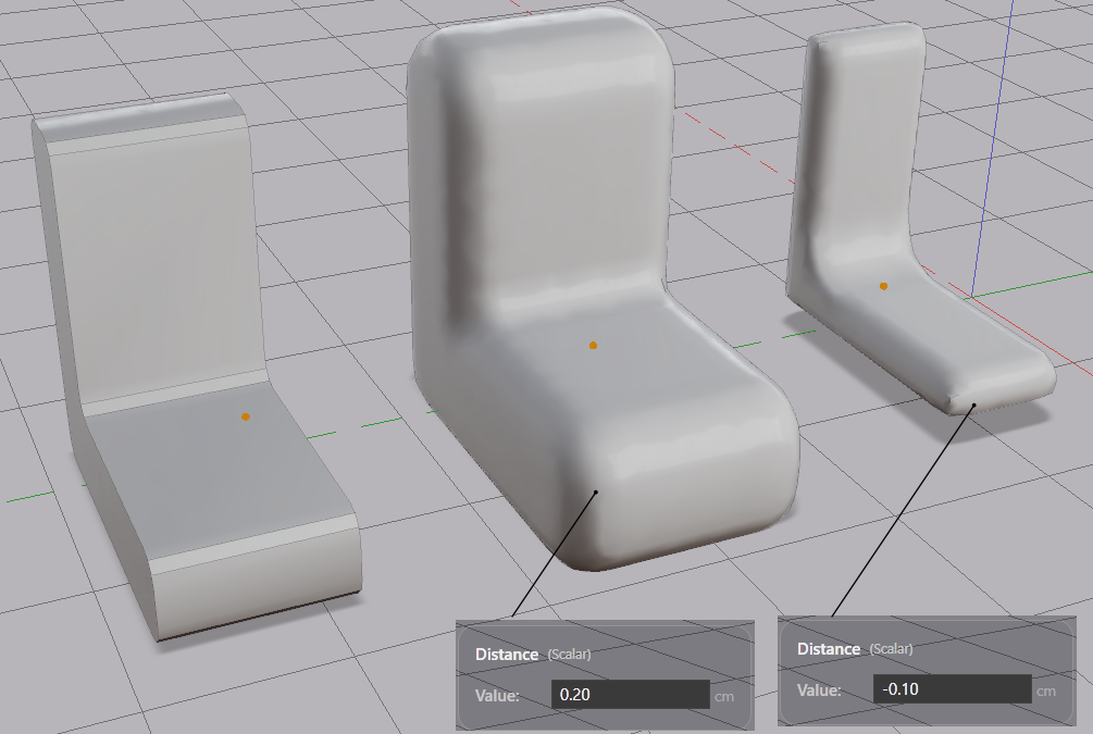
Surface offset inflates or deflates the whole surface of a shape by a set distance. You can use this for example to strengthen or thin a structural element. As a more involved example, a copy of a complex shape that is inset can be used to boolean cut a void inside the original piece.
Note: a large inward offset can erase the shape.
Boolean Blend
A boolean union normally meets in a sharp seam. Switch the union’s mode from Plain to Blend and the seam is rounded with a smooth fillet. The Blend Radius field controls its size.
Meld also bridges gaps. It joins all nearest areas from the two shapes with smooth necks.
Filleting corners with Blend can reduce the likelihood of the material cracking when stressed.
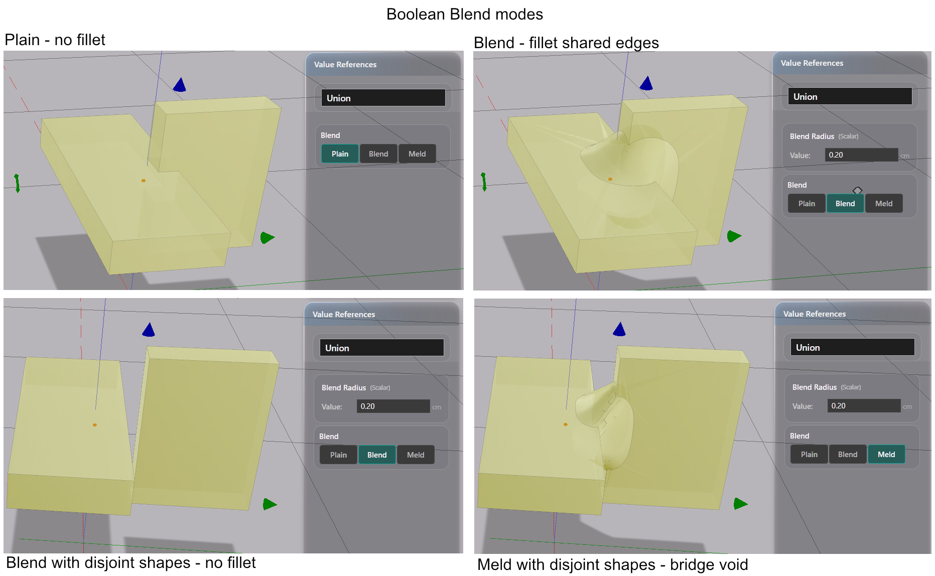
Blend and Meld apply to Union only.
Measure Tools
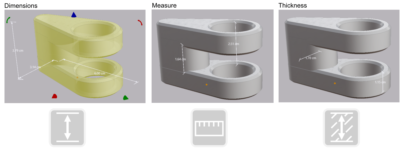
Four new tools measure distances, wall thickness, and display selected shape’s dimensions.
 |
Measure Distance between two points. |
 |
Thickness Click a surface to measure the solid thickness from that point. |
 |
Show Dimensions Display dimensions for the selected part |
 |
Clear Dimensions Clear all measurements |
Placement Orientation Modes
The move and rotate widgets by default are aligned with the world axes.
Two new modes allow the move and rotate widgets to follow the selected shape’s own local coordinate system, or the focus pointers.
A new toolbar button cycles three orientations for the movement widgets:
 |
Global Move and rotate along the world axes |
 |
Local Move and rotate along the selected shape's own axes |
 |
Focus Move and rotate along the focus pointer's frame |
Also in 0.2.0
Drawing Editor. A new mirrored drawing mode keeps a drawing symmetric. Boolean, Copy and Paste buttons now sit in the editor’s own toolbar, keyboard shortcuts like Ctrl+Z and Ctrl+V work inside the editor, and the toolbar buttons are larger.
Shapes with no presentation stay selectable. Some operations on shapes can make the valid surface disappear. An offset too far inward, for example. When a shape has no presentation, it is replaced by a selectable outline box. Correct the value in the sidebar and the shape returns in place.
WASD navigation in the main 3D view. W and S move the camera forward and back. A and D move it left and right.
Scale uniform toggle. The Scale operator can be set so that all three scales change as one, or each one changes individually.
Modify cube symmetrically. When symmetric editing for a cube is active, dragging either corner point changes the shape in both directions at once.
Do remember backups
AdaShape saves your full modeling history continuously to disk. Backups are still recommended as AdaShape is an offline solution and does not protect against local hardware failure.
To try this out: