Dimension Annotations
Dimension lines, radius marks, and diameter annotations shown on selected shapes in the Drawing Editor.
The Drawing Editor shows engineering-style dimension annotations on selected shapes. Annotations follow ISO 129 conventions: extension lines, arrowheads, and centered text. All values use the configured display unit.
Width and Height
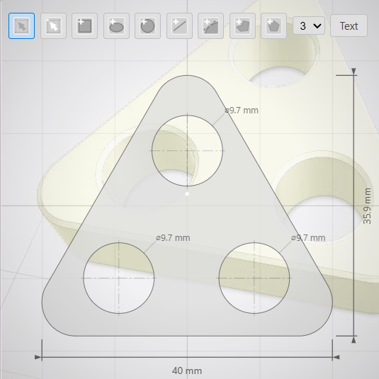
Selecting any shape displays width and height dimension lines. The width line appears below the shape’s bounding box; the height line appears to the right. Both include extension lines running from the shape’s edges to the dimension line.
Radius Marks
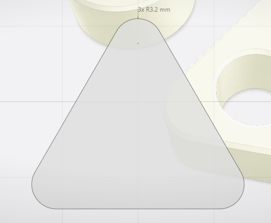
Rounded corners on polylines, polygons, and rectangles show ISO-style radius marks — a leader line with an arrowhead pointing to the corner arc, labeled with an R prefix and the radius value.
When multiple corners share the same treatment, their marks are grouped into a single label placed at the top-left corner to avoid crowding the dimension lines. For example, four corners all rounded to 3.5 mm appear as 4x R 0.35 cm. In Full mode, where corner radii vary proportionally, each distinct radius is annotated separately.
Circle Radius
Selected circles display a radius annotation: a leader line from the center to the edge, labeled with an R prefix.
Hole Diameters
Circular holes in boolean results display diameter annotations using the standard ⌀ symbol, alongside the centerline crosshairs that mark the hole center.
Drawings Mode
In Drawings mode, all shapes receive dimension annotations regardless of selection. This makes it straightforward to produce a fully dimensioned technical drawing — switch to Drawings mode, then export with Save Image.