Solid and Buffered Extrusion
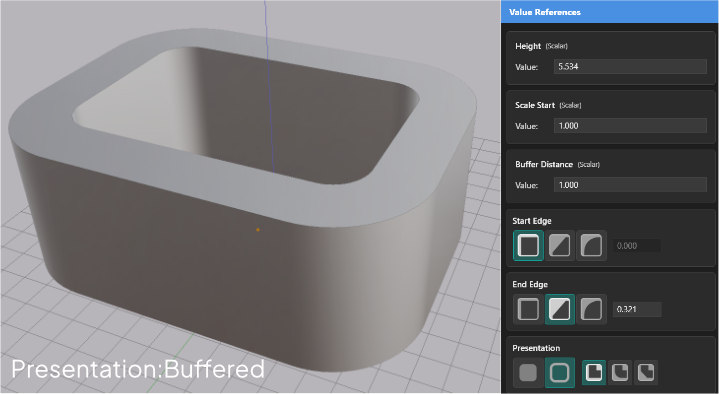
Choose between Solid (closed profiles become filled shapes) and Buffered (profile lines become walls with thickness).
Extrusions have two presentation modes: Solid and Buffered. The mode controls how the profile drawing is interpreted before it is extruded.
Select an extrusion, then use the Presentation row in the Value References panel to switch between them.
Solid Mode
Solid mode extrudes the profile as-is. Closed paths become filled cross-sections, and the result is a solid 3D shape. This is the default mode for profiles you draw in the Drawing Editor.
Use Solid mode when your profile already encloses the areas you want filled — outlines of letters, closed polygon silhouettes, logo shapes.
Buffered Mode
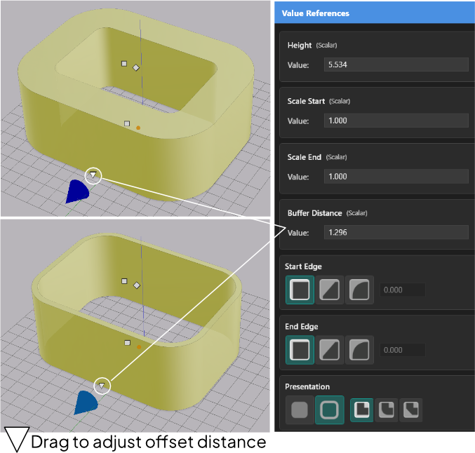
Buffered mode offsets the profile outward (and inward) before extruding. Every line in the drawing is treated as the centerline of a wall. The result has thickness — open paths become ribbons, closed paths become hollow outlines with walls.
Use Buffered mode when your profile contains open paths — lines, polylines, curves that do not close — or when you want an outline shape rather than a filled solid.
SVG files that contain open vector lines automatically start in Buffered mode. An open path cannot form a solid cross-section, so AdaShape switches to Buffered mode on update or close if only open paths are present.
Buffered Mode Parameters
| Parameter | What it controls |
|---|---|
| Buffer Distance | Wall thickness — how far the offset extends from each path centerline |
| Join Type | How corners are handled where paths meet |
| Miter Limit | Maximum extension of sharp miter joins before they are clipped |
Join Type Options
| Join Type | Result |
|---|---|
| Miter | Sharp corners — the offset edges meet at a point |
| Round | Smooth corners — the offset edges are joined by an arc |
| Bevel | Flat corners — the offset edges are joined by a straight cut |
Given a large enough Buffer Distance, walls from adjacent paths will merge together into a single mass.